
Preliminary Hazard Analysis in Aligned Elements

{fastsocialshare}

Preliminary Hazard Analysis is a risk assessment technique performed in the early design phases. It is a powerful method to document and assess device risks without having the full implementation completed and to highlight problematic risk areas early on.

hazard

We have previously discussed how the PHA compares with the FMEA method in Aligned Elements and how they complement each other. The templates needed are available here.

Learn more about Aligned Elements and Riskmanagement

Request a live demo and let us show you how Aligned Elements helps you with your Preliminary Hazard Analysis

The IEC 62304 Matrix Model in Aligned Elements

I say "IEC 62304 Software Safety Classification", you say "A, B, C".

If you have worked with IEC 62304, you have (probably) also faced the challenge of assigning Software Safety Classifications to the Software Items. It has to do with associating a risk level to your software items in order to assess how careful you need to be when you document, develop and test them.

Now, if you work with medical device development, it has probably dawned on you that you are already doing risk management. Lots of risk management. All sorts of risk management. Is it possible to use the existing risk assessments when doing our IEC 62304 work? Yes, I think so.

When a software designer/architect constructs the software architecture needed for IEC 62304, there are lots of approaches to choose from. The norm is explicitly ambiguous on this point. In short, it is up to you to pick an approach. It is however not uncommon for the software designer to use established modeling techniques such as UML, Object-oriented design, multi-layered design, SAAS, etc. which in most cases results in a number of boxes (the software items) with names like:

  • User Interface
  • Logging
  • User Management
  • Reporting
  • Data Access Layer
  • Persistence
  • Serial Communication etc.

So are we supposed to perform a risk assessment of these boxes now?

What strikes you immediately is the insight that these boxes in themselves do not "have" risk. Why? Because we have not defined the context in which they are used. Software risk emanates from how we use the software i.e. in which functional aspect we use the software items.

The guys of Certified Compliance Solution have solved this in a really neat way using what they call "The Matrix Model for Software Safety Classification". It is well summarized in the picture below.

MatrixModel


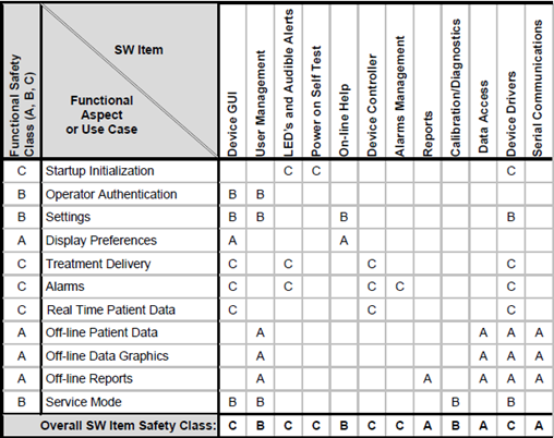
The CCE people have correctly identified that functional flows cut across the software architecture.

In their model, Software Items are listed on the horizontal axis, and User stories (or Epics, Use Cases, Work Flows, Specification, or whatever you want to call them) are listed on the vertical axis. Now, risk assessments for User Stories are something we do every day so that part should be pretty straight-forward. Once that is completed, we can deduct a classification for each User Story based on this risk assessment (more about that later).

The Software Designer can now point out the Software Items that implement our User Story in the software. After we have done this for all User Stories, the software Safety Classification for a Software Item is simply the highest risk of its aggregated use, which is summarized in the bottom line "Overall SW Item Safety Class".

Isn't it beautiful?

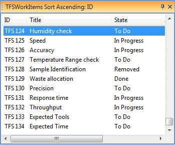
Let me show you how this is implemented in Aligned Elements.

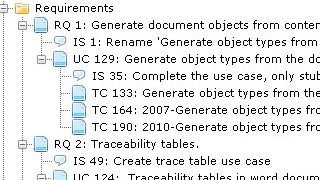
First, I introduce the Document Object type "Use Case" which will represent the user stories. Then I set up Document Object types for Software System, Software Item, Software Unit, and SOUP which all have a Software Safety Class attribute being A, B, or C, with the default value C.

I can then proceed to document the Use Cases and structure the Software Architecture separately.

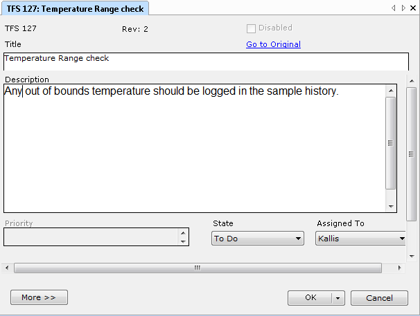
Now, time for risk assessment. I will use the integrated Preliminary Hazard Analysis (PHA) to assess my Use Cases. When working out the risks using the PHA method, I am requested to define the possible Cause(s) for each risk. The Cause has a severity attribute and I will use this severity to calculate the Software Safety classification. If the Cause is emanating from the software, I further tag the Cause originator as "Software".

62304RA

I go back to the Software Item definition and map the values A, B, and C to a Severity range in the Cause i.e. a Severity from 1-3 maps to Class A, Severity 3-5 maps to Class B, etc.

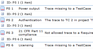
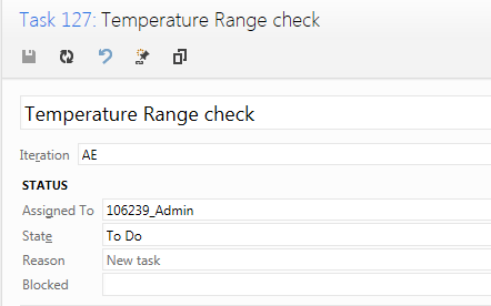
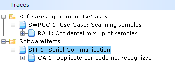
To tie it all together, I trace the Use Cases to the PHA risks and (here comes the trick) Software Items to the software originated Causes.


62304UseCaseTrace


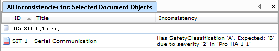
I run an Inconsistency analysis on the Software Items and get a report on how well the Software Item Safety classifications match the risk assessment, including suggestions on what the Software Safety Classification ought to be based on the associated risks.


62304SWItemInconsistency


Simple, transparent, and consistent.

So we have a range of benefits from this approach:

  • We perform risk assessment where it makes sense i.e. to Use Cases.
  • When we map use cases to software items via the risks, automatic checks will ensure that the maximum severity of the risks matches with the software item safety class.
  • We have reused the use case risk assessment in our IEC 62304 implementation.
  • We have used traces to establish the relationships between use case, risk and software items and automatically get the required traceability for free.

Once again we have shown the benefit of integrating all Design Control Items in a single system.

The sum is truly greater than its parts.

{fastsocialshare}


Traceability in Medical Device Development

Traces are the glue.

Traces are the links that tie the development documentations together. They provide the basis for verifying completeness and consistency.

Traceability, the discipline of setting and managing traces, is a core activity in the medical device development process. Norms and directives such as ISO 13485, ISO 14971, IEC 62304, IEC 62366 and FDA CFR 21 QSR 820 explicitly prescribe it.

Traces in a medical device project

In essence, establishing traces between artefacts is a deceptively straightforward task. You just declare the trace and that's it. So why is traceability perceived as such as an annoying piece of work?

The main reason is change.

As mentioned above, a trace establishes a relation between dependent artefacts (e.g. a requirement and a specification). When change occurs to one party in this relationship (the requirement), the state of the traced artefact (the specification) may become invalid.

Word documents and Excel sheets are notoriously inept at handling this kind of problem since the artefacts are not aware of each other.

Traces in an Excel sheet are just dead text.

On the other hand, this is why traceability software tools such as Aligned Elements are so popular. Traceability software tools not only allow traces to be declared but are also able to track changes made to the traced artefacts.

A change in an artefact automatically highlights the affected traces and signalizes that they might have become invalid due to the change. In Aligned Elements, we call such a possibly invalidated relationship a "suspect trace".

The user now has the possibility to inspect the implicated artefacts and update them if needed. Or simply confirm that the change did not have any impact on traced artefacts. In Aligned Elements, an impact analysis entry is made in the audit trail as the user completes this action, in order to ensure accountability throughout the development process.

However, these gains are quickly lost if different artefact types (e.g. tests and risks) are kept in separate systems. Managing traces across system boundaries is often only possible by resorting to manual measures. Such as Excel. And then we are back to where we started.

Keeping all traced artefacts in a single system further helps to disentangle a range of more mundane problems, such as finding out:

  • If some artefacts have not been traced
  • If some artefacts trace to artefacts of the wrong type
  • If some traces simply don't make sense

Trace consistency

In Aligned Elements, we have implemented traceability support following a few simple guidelines:

  • Usability. It shall be easy to set or remove a trace, regardless of the working context. Therefore we have five different mechanisms for setting traces.
  • Accountability. All trace-related operations shall be recorded chronologically in the audit trail.
  • Transparency. Missing, illegal and suspect traces must be immediately and automatically highlighted.
  • Completeness. End-to-end traceability must be facilitated without having to cross-system boundaries.
  • Reportability. Trace reports shall be customizable and configurable to match the quality requirements and look-and-feel criteria of each customer.

Again, traces are the glue.

Managed correctly with the right ALM support, they are (besides being regulatory necessities) a real asset to your design history file management. The traces help you ensure that completeness and consistency have been achieved throughout your development documentation. We are doing our best to make sure this becomes a smooth journey.

{fastsocialshare}

Efficient test case writing and execution

Not long ago, I sat down with three test managers I have recently worked with. They all have extensive backgrounds in managing test teams and supervise the writing and execution of test cases in large Medical Device projects. Since we have made the observation that about 50% of the total DHF is consisting of tests, I had long been pondering how the test activities could be done more efficiently.

We talked about how to find the right "review and release" effort (goldilocks principle, "not too much, not too little"), the optimal test case size, the optimal number of fields in a test case, and how to deal with the ever reoccurring problem of volatile specifications. I got some interesting input on all topics and I was very satisfied with how the conversation went on.

After a while, one of them said, "Mr. Larsson, it is all well and good that you want to optimize the test case writing and execution. I understand your intentions. But, you know, testing is more than just writing and executing. In my opinion, only 30% of the total test effort consists of the writing and execution activities you talk about. 70% is about setting the table. If I were you, I would take a look at that 70%."

Only 30% of the test effort is about writing test cases

I must confess that I did not really understand what he was talking about. In my world, testing is writing and executing test cases. And what did he mean by "setting the table"?

After some prying, we got closer to the heart of the matter: setting the table implies activities such as:

  • Setting up infrastructure (computers, user accounts, instruments, etc.)
  • Training testers – get to know the instrument, the “lingo”, the templates, and the processes
  • Setting up / calibrating the instruments to test
  • Learning simulation tools, log parsers, etc.
  • Generating test data
  • Reviewing specs
  • Dry runs and exploratory testing
  • Collecting test data

These are all auxiliary test activities that lay the foundation on which efficient test case writing and execution are subsequently performed. They might not look particularly impressive at first, but experience has shown that performing these activities carefully, consciously, and consistently pays off immensely. The reverse is also true; failing to give these activities their proper attention will have a severe impact on testing efficiency.

Finally, another test manager said, "Writing and executing a test case is the end of a long journey. It is the result of a long array of preparatory activities. It is how you get to this point that decides how efficiently your writing and execution will be".

{fastsocialshare}

How far is possible?

We have been following an interesting discussion on Linked In "How far is possible"  (this link can only be viewed if you are a group member: Medical Devices: QA / RA discussion 'How far is possible?') as a result of the 14971:2012 Annex ZA deviation #3.

In this discussion, Mr. Singh linked to an informative presentation http://goo.gl/QJiUZj on the subject.

Most companies that participated in the discussion have updated their processes to avoid the term ALARP, usually also no longer identifying any 'Acceptable' ranges of risks. The driver seems rather be to comply with what notified bodies expect to see. All still acknowledge that there will always be the notion of an economical parameter when deciding on risk measures. The arguments backing why the risk measures weren't taken even further were recommended to be an analysis of Risk vs Benefit and claiming that the risk measures are 'State of the Art'


howFarIsPossible


 {fastsocialshare}


Integrating TFS with Aligned Elements

Since the release of Aligned Elements V2.1 SP 1, it is possible to integrate Work Item lists from your existing Team Foundation Server in Aligned Elements.

With the appropriate configuration, coupling your Aligned Elements user with your TFS user, your Work Items dynamically appear in a separate Item view. 

TFS

In Aligned Elements, the Work items behave and are treated very much like regular Document Objects, meaning that you can open and edit them in a Document Object form, set traces to them, set up inconsistency rules for real-time checks, etc.

TFS2

When saving changes made to a Work Item in Aligned Elements, the attribute changes are routed to the TFS server, effectively separating the two repositories according to their respective responsibilities. 

Using the "Go to Original" link in the Document Object Form automatically opens a browser and navigates to the Work Item on your TFS server.

TFS3

Using the Aligned Element TFS integration permits you to benefit from your existing Team Foundation System infrastructure in the Design History File management, working smoother, faster, and with fewer interruptions.

{fastsocialshare}